45 in 1
Elements:
Chip signature:
PCB top:
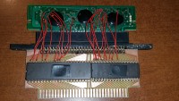
PCB bottom:

Shell top:
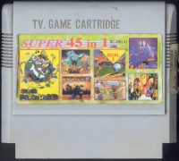
Shell bottom:

Screenshoots:
No photo
Extra info:
[fixing + analysis] JY-120 45-in-1

I have received another JY-120 45-in-1 broken cartridge.
[url=https://obrazki.elektroda.pl/6231478900_1561104405.jpg][img]https://obrazki.elektroda.pl/6231478900_1561104405_thumb.jpg[/img][/url] [url=https://obrazki.elektroda.pl/5296419800_1561104407.jpg][img]https://obrazki.elektroda.pl/5296419800_1561104407_thumb.jpg[/img][/url] [url=https://obrazki.elektroda.pl/6379719600_1561104412.png][img]https://obrazki.elektroda.pl/6379719600_1561104412_thumb.jpg[/img][/url] [url=https://obrazki.elektroda.pl/2028811800_1561105949.jpg][img]https://obrazki.elektroda.pl/2028811800_1561105949_thumb.jpg[/img][/url] [url=https://obrazki.elektroda.pl/1088533700_1561105954.jpg][img]https://obrazki.elektroda.pl/1088533700_1561105954_thumb.jpg[/img][/url]

[b]Fixing[/b]
Quick test in Kazzo shown that reading from CPU returns $00 not only at $8000-$FFFF, but also below $6000 (so does for PPU). Because CPU and PPU buses are wired together in Kazzo, I had 3 suspects:
* PRG ROM chip is broken and drives data bus despite being disabled,
* CHR ROM chip is broken and drives data bus despite being disabled,
* Mapper blob is broken (either it drives data bus all the time or the lines controlling PRG/CE or CHR/CE are broken).

I quickly measured voltages at PRG/CE and CHR/CE and they were +5V when the ROMs should be disabled. Next I glued transparent tape on the PPU-D0..7 pins in the edge connector to prevent interaction from CHR-ROM and still there was $00. I measured the CHR-ROM side of pins and they were different.

So CHR-ROM **might** be ok. I managed to cut the tracks that connect to the PRG-ROM chip and bingo - no more 00 on data bus!
[url=https://obrazki.elektroda.pl/1591450300_1561055905.jpg][img]https://obrazki.elektroda.pl/1591450300_1561055905_thumb.jpg[/img][/url]

Next I made a quick test to the mapper registers and I've found out that:
+ internal multiplier worked,
+ IRQ worked,
+ forcing each of the PRG-A12..A20 and CHR-A10..A18 pins to drive 1/0 also succeeded
- CHR-A19 seemed to be at 0.2V (disconnected?).
- CHR/CE sometimes on power-up was enabled for $2000-3fff.
- CHR-ROM did not give consistent read results (maybe because of the floating CHR-A19 pin??)

So the conclusion was that:
* PRG-ROM is definitely broken,
* maybe mapper chip was not 100% reliable,
* CHR-ROM is state is still unknown.

The solution was to project an add-on board that would:
* have cartridge connector that original JY-120 would plug in, allow to solder some wires and then plug everything into console (something like Game Genie),
* fit into original shell (luckily it is larger than normal)
* contain 2MB PRG-ROM
* contain FPGA to fix broken functionality of mapper if any is discovered.

Because of the over 1MB ROM chip, I had to use 27C322 EPROM. Believe me or not, but projecting the PCB to make every line go from edge to edge and also go to memory and FPGA was nightmare. And also I had to do it in that way so ROM chip is only soldered from bottom side, otherwise I wouldn't be able to desolder it without damaging PCB (that's why there are a lot of vias)
I had to shuffle data and address pins to make the layout as simple as possible.

[url=https://obrazki.elektroda.pl/4437427500_1561104948.jpg][img]https://obrazki.elektroda.pl/4437427500_1561104948_thumb.jpg[/img][/url]  [url=https://obrazki.elektroda.pl/8188831500_1561056464.png][img]https://obrazki.elektroda.pl/8188831500_1561056464_thumb.jpg[/img][/url] [url=https://obrazki.elektroda.pl/2733203800_1561056468.jpg][img]https://obrazki.elektroda.pl/2733203800_1561056468_thumb.jpg[/img][/url] [url=https://obrazki.elektroda.pl/6237317400_1561056475.jpg][img]https://obrazki.elektroda.pl/6237317400_1561056475_thumb.jpg[/img][/url] [url=https://obrazki.elektroda.pl/2355348200_1561056479.jpg][img]https://obrazki.elektroda.pl/2355348200_1561056479_thumb.jpg[/img][/url] [url=https://obrazki.elektroda.pl/4488050600_1561056942.png][img]https://obrazki.elektroda.pl/4488050600_1561056942_thumb.jpg[/img][/url]

It did not work from first run (I had to desolder the ROM chip 3 times and reprogram it cause of my mistakes and also poor documentation of this ROM), but finally I was able to make game boot!
https://www.youtube.com/watch?v=BYLg17ARHOY

Unfortunately there were some artifacts - probably because CHR-ROM was also broken. Fortunately I found out that I am able to control CHR-A19 and also CHR-ROM enabling at $2000-$3fff is not a bug (will describe that later). So this add-on PCB is useless and I had to project and make second one - containing PRG-ROM and CHR-ROM (FPGA for mapper seemed to be unnecessary).
[url=https://obrazki.elektroda.pl/3556530400_1561057088.jpg][img]https://obrazki.elektroda.pl/3556530400_1561057088_thumb.jpg[/img][/url] [url=https://obrazki.elektroda.pl/2381188400_1561057086.jpg][img]https://obrazki.elektroda.pl/2381188400_1561057086_thumb.jpg[/img][/url] [url=https://obrazki.elektroda.pl/2031085200_1561057152.png][img]https://obrazki.elektroda.pl/2031085200_1561057152_thumb.jpg[/img][/url]

Luckily this time everything worked!

--
[b]Analysis[/b]

[b]Ok, so now my few words about the game (45-in-1 (Unl) (As) [f1].nes):[/b]
* Only the second megabyte of the CHR-ROM is correct (NewRisingSun pointed that out before),
* PRG-A19 and PRG-A20 lines were swapped when dumping the PRG part, causing second and third 512kB bank to be swapped (well, this might be philosophic question which one is which, but if assuming my order, then:
-mapper blob PRG-A12..A20 are perfectly in order
-PRG-ROM blob pinout matches exactly the 27320 pin-out.

[b]Few notes about the register at $D003 which control outer banks:[/b]
[code]
  001?000 <- power up state
[abcdefgh]
 ||||||||
 |||||||+- chr-a18 (*)
 ||||||+-- prg-a20 (**)
 |||||+--- prg-a19
 ||||+---- chr-a19
 |||+----- 1=chr-a19 becomes open bus (0.2V) - e bit is ignored
 ||+------ prg-a20, chr-a18 (*) (**)
 |+------- 1=prg-a19 becomes open bus (0.2V) - f bit is ignored
 +-------- 1=MMC4 banking mode
[/code]
(*) (**) There are two bits controlling CHR-A18 and PRG-A20. The resulting value is OR of them.
I first thought that one of them might be used to choose the PRG and CHR mask, but setting all the PRG $8000-$8003 and CHR $9000-$9007 banks to 0 or FF did not change anything.

[b]Few notes about the PCB:[/b]
* Despite CIRAM/CE being connected to PPU/A13, $D000.5 is still able to enable the ROM for $2000-$3fff.
There is a weird trace to nowhere that goes one side to PPU /A13, the other side to jumper and blob
[url=https://obrazki.elektroda.pl/8943660800_1561105114.png][img]https://obrazki.elektroda.pl/8943660800_1561105114_thumb.jpg[/img][/url]

[b]Few notes about the IRQ Counter:[/b]
I was curious to check how the "funky" bit affects the IRQ counter, but before that I found out that the currently described IRQ counter behavior is not 100% correct.

All tests were performed using MyKazzo and IRQ clock source was selected as `PPU reads` (this way, any additional CPU writes to mapper registers does not affect IRQ accuracy).

[code]
$C006 <- $00       //xor       | all those five writes
$C002 <- $00       //irq dis   | will preceed
$C003 <- $00       //irq en    | every test,
$C007 <- $00       //funky reg | so I won't
$C001 <- $00       //mode      | write them again

$C001 <- %10000010 //mode D
$C005 <- $01       //counter
$C004 <- $05       //prescaler
//$106  reads need to be done before IRQ is triggered, so everything seems to be OK

$C001 <- %01000010 //mode U
$C005 <- $fe       //counter
$C004 <- $fa       //prescaler
//$106  reads need to be done before IRQ is triggered, so everything seems to be OK

$C005 <- $01       //counter
$C004 <- $05       //prescaler
$C001 <- %10000010 //mode D
//$105

$C005 <- $01       //counter
$C004 <- $05       //prescaler
$C001 <- %10000010 //mode D
$C005 <- $01       //counter
//$105

$C005 <- $01       //counter
$C004 <- $05       //prescaler
$C001 <- %01000010 //mode U
$C001 <- %10000010 //mode D
//$107

$C005 <- $01       //counter
$C004 <- $05       //prescaler
$C001 <- %11000010 //mode U+D
$C001 <- %10000010 //mode D
//$107

$C005 <- $01       //counter
$C004 <- $05       //prescaler
$C001 <- %01000010 //mode U
$C001 <- %10000010 //mode D
$C001 <- %01000010 //mode U
$C001 <- %10000010 //mode D
//$107

$C005 <- $fe       //counter
$C004 <- $fb       //prescaler
$C001 <- %01000010 //mode U
//$104

So assuming that:
* writes to C004/C005 directly alters the current prescaler/counter with the value written,
* when prescaler wraps, counter is clocked and when counter wraps, IRQ is fired

I think that:
* When $c004 is written, flag1 is set
* when $c001 is written:
  * if DU=01 and flag1 is set -> flag1 is cleared, prescaler is increased by 1 (buggy)
  * if DU=11 and flag1 is set -> flag1 is cleared, prescaler is increased by 1 (buggy)
  * if DU=10 and flag1 is set -> flag1 is cleared, prescaler is decreased by 1 (even more buggy)
  * if DU=00                  -> flag is not cleared, prescaler is not changed

There are more detailed look at the bugs in increase/decrease (! = buggy result, * = 0..$f)

$C005 <- $00       | $C005 <- $ff        | $C005 <- $00       | $C005 <- $ff          | $C005 <- $00        | $C005 <- $ff
$C004 <- $x        | $C004 <- $x         | $C004 <- $x        | $C004 <- $x           | $C004 <- $x         | $C004 <- $x
$C001 <- %10000010 | $C001 <- %01000010  | $C001 <- %01000010 | $C001 <- %10000010    | $C001 <- %11000010  | $C001 <- %11000010
                   |                     | $C001 <- %10000010 | $C001 <- %01000010    | $C001 <- %10000010  | $C001 <- %01000010
//$y reads         | //$y reads          | //$y reads         | //$y reads            | //$y reads          | //$y reads
                   |                     |                    |                       |                     |
x   | y            |  x   | y            | x   | y            | x   | y               | x   | y             | x   | y
----+---           |  ----+---           | ----+---           | ----+---              | ----+---            | ----+---
$*0 | $*c       !  |  $*0 | $*f          | $*0 | $*2          | $*0 | $*5             | $*0 | $*c       !   | $*0 | $*5
$*1 | $*1          |  $*1 | $*e          | $*1 | $*3          | $*1 | $100 - $*0 !    | $*1 | $*3           | $*1 | $*e
$*2 | $*2          |  $*2 | $*d          | $*2 | $*4          | $*2 | $*f             | $*2 | $*2       !   | $*2 | $*f
$*3 | $*3          |  $*3 | $*c          | $*3 | $*5          | $*3 | $*e             | $*3 | $*5           | $*3 | $*c
$*4 | $*8       !  |  $*4 | $*b          | $*4 | $*6          | $*4 | $*9        !    | $*4 | $*8       !   | $*4 | $*9
$*5 | $*5          |  $*5 | $*a          | $*5 | $*7          | $*5 | $*c             | $*5 | $*7           | $*5 | $*a
$*6 | $*6          |  $*6 | $*9          | $*6 | $*8          | $*6 | $*b             | $*6 | $*6       !   | $*6 | $*b
$*7 | $*7          |  $*7 | $100 - $*0 ! | $*7 | $*1       !  | $*7 | $*a             | $*7 | $*1       !   | $*7 | $100 - $*0
$*8 | $*4       !  |  $*8 | $*7          | $*8 | $*a          | $*8 | $*d        !    | $*8 | $*4       !   | $*8 | $*d
$*9 | $*9          |  $*9 | $*6          | $*9 | $*b          | $*9 | $*8             | $*9 | $*b           | $*9 | $*6
$*a | $*a          |  $*a | $*5          | $*a | $*c          | $*a | $*7             | $*a | $*a       !   | $*a | $*7
$*b | $*b          |  $*b | $*4          | $*b | $*d          | $*b | $*6             | $*b | $*d           | $*b | $*4
$*c | $*0 + $10 !  |  $*c | $*3          | $*c | $*e          | $*c | $*1        !    | $*c | $*0 + $10 !   | $*c | $*1
$*d | $*d          |  $*d | $*2          | $*d | $*f          | $*d | $*4             | $*d | $*f           | $*d | $*2
$*e | $*e          |  $*e | $*1          | $*e | $*0 + $10 !  | $*e | $*3             | $*e | $*e       !   | $*e | $*3
$*f | $*f          |  $*f | $*8        ! | $*f | $*9          | $*f | $*2             | $*f | $*9       !   | $*f | $*8

--

Now lets turn on prescaler mask ($C001.2 = 1).
If we first write to $C001, then set $C004 - it works as expected.
But when doing the opposite - thing will start even more weird:

$C005 <- $00         | $C005 <- $00         | $C005 <- $00         | $C005 <- $00
$C004 <- $x          | $C004 <- $x          | $C004 <- $x          | $C004 <- $x
$C001 <- %10000110   | $C001 <- %01000110   | $C001 <- %01000110   | $C001 <- %10000110
                     |                      | $C001 <- %10000110   | $C001 <- %01000110
//irq after $y reads | //irq after $y reads | //irq after $y reads | //irq after $y reads
                     |                      |                      |
x   | y              | x   | y              | x   | y              | x   | y
----+---             | ----+---             | ----+---             | ----+---
$*0 | never          | $*0 | $10            | $*0 | $a             | $*0 | $e
$*1 | $1             | $*1 | $7             | $*1 | $3             | $*1 | $1
$*2 | $2             | $*2 | $6             | $*2 | $4             | $*2 | $8
$*3 | $3             | $*3 | $5             | $*3 | $5             | $*3 | $7
$*4 | $8             | $*4 | $4             | $*4 | $6             | $*4 | $2
$*5 | $5             | $*5 | $3             | $*5 | $7             | $*5 | $5
$*6 | $6             | $*6 | $2             | $*6 | $8             | $*6 | $4
$*7 | $7             | $*7 | $1             | $*7 | $1             | $*7 | $3
$*8 | never          | $*8 | $10            | $*8 | $a             | $*8 | $e
$*9 | $1             | $*9 | $7             | $*9 | $3             | $*9 | $1
$*a | $2             | $*a | $6             | $*a | $4             | $*a | $8
$*b | $3             | $*b | $5             | $*b | $5             | $*b | $7
$*c | $8             | $*c | $4             | $*c | $6             | $*c | $2
$*d | $5             | $*d | $3             | $*d | $7             | $*d | $5
$*e | $6             | $*e | $2             | $*e | $8             | $*e | $4
$*f | $7             | $*f | $5             | $*f | $5             | $*f | $3

| $C005 <- $00
| $C004 <- $x
| $C001 <- %01000110
| $C001 <- %10000010
| //irq after $y reads
|
| x   | y
| ----+---
| $*0 | $102
| $*1 | $3
| $*2 | $4
| $*3 | $5
| $*4 | $6
| $*5 | $7
| $*6 | $8
| $*7 | $1
| $*8 | $10a
| $*9 | $b
| $*a | $c
| $*b | $d
| $*c | $e
| $*d | $f
| $*e | $10
| $*f | $d


never = something gets locked inside and irq will never be triggered.
Disabling or enabling IRQs, writing to $c004 with different value or
writing to $c001 with bit 2 cleared does not help.
The only way to unlock is to write to $c005 (written value can be the same as before).
This is strange cause writing to $c005 does not seem to clear the prescaler (either when $c001.2=0 or =1)

--

$d001.3 a'ka Funky Mode

When D001 is written with bit 3 set:
* if DU = 10 and $c005 is $0 -> IRQ is asserted immediately
* if DU = 01 and $c005 is $FF -> IRQ is asserted immediately
* if DU = 11 and $c005 is 0 or $FF -> IRQ i asserted immediately
If IRQs will be disabled and then enabled, IRQ is again asserted - Funky Mode bit makes the IRQ to be generated not when counter wraps, but when it holds the maximum/minimum value according to the counting direction)

* every time a clock is generated, prescaler is decreased (or increased - according to direction), but wrapping of prescaler does not cause counter to increase/decrease

* if Funky Mode bit is set, and then cleared, counter is increased/decreased, depending how the DU bits as follows:
$C005 <- $02 //counter
$C004 <- $05 //prescaler
$C001 <- %ab000110
$C001 <- %cd000010
$C001 <- %10000010
//#number of reads

 \ab 00   01   10   11
cd\
00 $206 $307 $105 $107
01 $306 $307 $105 $107
10 $106 $107 $106 $107
11 $106 $107 $106 $107

Despite what kevtris wrote and what I found in the Dish mapper docs, I am unable to:
* force $c007 to have any effect for the FunkyMode or anything else,
* clock the counter when in Funky Mode (even if $c007=$ff)
[/code]
Comments:
Want to leave a comment?