Shell bottom: No photoScreenshoots: No photoExtra info:
http://forums.nesdev.com/viewtopic.php?f=9&t=19309
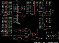
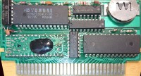
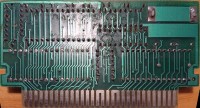
[url=https://obrazki.elektroda.pl/4943652900_1569007223.jpg][img]https://obrazki.elektroda.pl/4943652900_1569007223_thumb.jpg[/img][/url] [url=https://obrazki.elektroda.pl/4927691000_1569008045.jpg][img]https://obrazki.elektroda.pl/4927691000_1569008045_thumb.jpg[/img][/url] [url=https://obrazki.elektroda.pl/9633304400_1569008048.png][img]https://obrazki.elektroda.pl/9633304400_1569008048_thumb.jpg[/img][/url]
[code]
fedbca9876543210
A~[100....P.PPPPpMv] (initialized to zeros on powerup & soft reset)
| |||||||
| ||||||+- 0=16K, 1=32K
| |||||+-- 0=V, 1=H
| |||||
+-+++++--- PRG-A19..A14 (p ignored in 32K mode)
++---- RAM-A14..A13 ??
+--- when 1 - locks further writes until powerup/soft reset
[/code]
My doubts/quirks:
* The register is present only at $8000-$9fff,
* There are bus conflicts
* there might be one or two bits controlling WRAM (vias for both PRG-A15 and PRG-A14 suspiciously are present under RAM chip)
* /CS of WRAM is pulled-up to VCC, not the battery backed up voltage (does savestate corruption occur?)
* instead of M2, /RESET is taken into decoding of WRAM /CS (might be more corruption-proof?)
* setting the p bit permanently locks any further writes (no matter if it is in 32K or 16K mode), so the only way of dumping it is to use 32K banks and keep this bit always at 0.
* are both VCC pins (30, 31) shorted?
* rightmost resistor (R2=4.7k) pulls up something to VCC but I dont have idea what (is it placed between GND and VCC?)